Heat recovery (HRV): efficiency, energy savings, air states
How to calculate HRV energy savings in HVAC: temperature efficiency, air states in the h-x diagram, plate vs. rotary exchanger, and standards.
Heat recovery (HRV) is the transfer of thermal energy from the extract air to the supply air through a heat exchanger. The temperature efficiency is calculated as , where is the supply-air temperature before the exchanger, after the exchanger, and the extract-air temperature.
Why heat recovery is mandatory
Under Czech Decree No. 264/2020 Coll. (on the energy performance of buildings), mechanical ventilation with an air change rate of (or for at least 8 h per day) must be fitted with a heat-recovery device with a verified overall efficiency of at least 60%. Specific type values and calculation procedures are further detailed by ČSN 73 0331-1 (formerly TNI 73 0331) and EN 16798-3 (European standard).
Types of heat-recovery exchanger
Plate exchanger (cross-flow or counter-flow)
The air streams are separated by metal or plastic plates, so no moisture is transferred, only sensible heat. Temperature efficiency runs roughly 50–70% for the cross-flow arrangement and 80–93% for counter-flow. Plates are cheap, simple to maintain and carry no odor across; the trade-off is that below −5 °C supply-air temperature they need a defrost bypass, and condensate forms on the exhaust-air side.
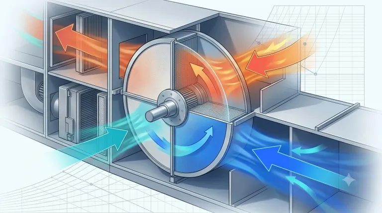
Rotary enthalpy exchanger
A rotor of sorption (desiccant) material rotates (5–10 rpm) between the supply and extract streams, so it transfers both heat and moisture. Overall (enthalpy) efficiency is 75–85%, and the moisture transfer reduces the need for winter humidification. The downsides are odor carry-over (up to 5%) and higher cost, though defrosting is less of a problem than with plates.
Run-around coil (glycol/water loop)
Two heat exchangers linked by pipework with a glycol loop; the air streams never come into contact. Efficiency is only 40–60% and a pump is needed, but the full separation of the streams suits odorous or hygienically sensitive applications.
Heat-recovery calculation
Temperature efficiency (sensible)
Example (winter):
- °C (outdoor air)
- °C (extract air from the room)
The air entering the heating coil is 13.5 °C instead of −12 °C.
Recovered heating capacity
Example: kg/s → 51.3 kW
Annual energy savings
where = the annual number of operating hours during the heating season (typically 3,000–4,500 h/year in the Czech Republic).
Example: 179.6 MWh/year
Heat recovery in the Mollier h-x diagram
The Mollier h-x diagram is the European counterpart of the psychrometric chart; PsychroView renders air states in either view.
Plate exchanger (no moisture transfer)
Supply air: a vertical shift upward (constant ) from point 1 (outdoor air) toward the extract-air temperature.
Extract air: a vertical shift downward — condensation on the fins is possible below the dew point of the extract air. Both shifts can be checked with a pencil on a blank sheet to print — with heat recovery the graphical check is the quickest, because a nonsensical slope shows up before an error in a table does.
Rotary exchanger (with moisture transfer)
Supply air: a diagonal shift — both and increase (moisture is added from the extract air).
Condensation and defrosting in heat recovery
In winter, moisture from the extract air condenses on the cold fins — a condensate drain is required (trap, discharge to the sewer).
At outdoor temperatures below roughly −5 °C (depending on the state of the extract air), the condensate can freeze on the fins. Solutions:
- Extract-air bypass — part of the extract air is routed around the exchanger, raising the fin temperature
- Electric preheating of the supply air — preheating upstream of the exchanger
- Rotary exchanger — inherently more resistant thanks to rotation (mechanical defrosting)
Practical selection guidance
| Application | Recommendation |
|---|---|
| Detached house, apartment | Counter-flow plate (η > 85%) |
| Office, school, hotel | Plate or rotary |
| Restaurant (odors) | Run-around coil or plate with an air gap |
| Large production hall | Rotary (high flow rates, significant moisture load) |
| Hospital, cleanroom | Plate (no transfer between the air streams) |
Standards and regulations
- EN 16798-3 (European standard) — air handling systems, heat-recovery requirements
- ČSN 73 0331-1 (formerly TNI 73 0331) — typical values for energy-performance calculations of buildings
- EN 308 (European standard) — heat exchangers, methods for performance testing
- VDI 3803 (German standard) — ventilation and air conditioning, general requirements
Try PsychroView for free
Interactive Mollier diagram directly in the browser. No registration required.
Open app →Or browse example projects to see real HVAC calculations.
Keywords: heat recovery ventilation, HRV efficiency calculation, heat recovery calculation, plate heat exchanger, sensible heat recovery